Refrigeration Retrofit: installing Copeland variable frequency drives, EVM series

*On June 1, 2023 Emerson’s Climate Technologies business became a new standalone company – Copeland. Though our name has changed, we are building on more than a century of HVACR innovation and industry leadership, and Copeland continues to offer the same products, industry stewardship, and learning opportunities you’ve grown to trust. Information found on this webpage posted before June 1, 2023 may contain our old name or branding, but you can be at ease knowing it was created with the knowledge and expertise of Copeland.
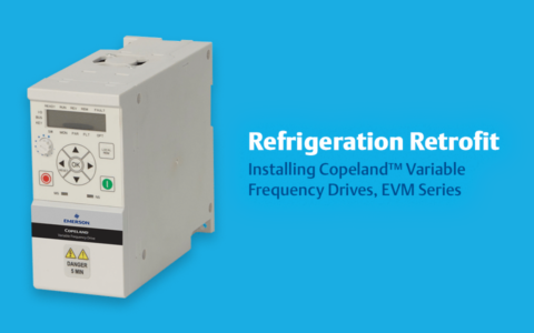
Many supermarket and facility operators are looking for opportunities to retrofit their existing HVACR equipment to improve energy efficiency, reliability and performance. With the recent launch of Copeland™ variable frequency drives (VFDs), EVM Series, contractors have new opportunities to help their customers achieve these goals. In fact, our EVM Series drives can be installed on existing fixed-speed HVACR motors without having to swap out or replace equipment, resulting in faster and more affordable retrofits.

I recently produced an instructional video to cover EVM Series installation best practices within a refrigeration rack and demonstrated their user-friendly startup wizard.
Unboxing your EVM drive
Before you begin the installation process, it’s important to make sure that you have the correct model and verify that it did not incur any damage during shipping.
-
- Remove the drive from the box and verify that the model number on the nameplate matches what’s on the shipping box label.
- Inspect the drive to ensure there are no cracks and/or visible damage.
- Review the quick-start guide, and follow the quick-start guide and installation manual during installation.
Installation and mounting considerations
Choosing an installation location is key to protecting the drive and enabling easy access to it and the compressors in the rack.
-
- Identify the fixed-speed lead compressor that will be retrofitted.
- Select a location to install the drive where it will not be exposed to moisture (from weather, refrigeration chiller lines or potential leaks) or excess vibration (from placement within the rack).
- Choose a location that won’t restrict access to compressors in the rack or make it difficult to interface with the drive itself (e.g., too high). An ideal location for many applications is within an electrical panel mounted on a din rail for ease of access.
Wiring and connections
EVM Series drives are designed with easily accessible input/output (I/O) terminals and provide a quick reference of their locations on the inside cover panel of each drive. Making connections requires only two flathead screwdrivers: one for the controller wire and one for incoming/outgoing compressor wire connections. Before making electrical connections, be sure to follow proper lockout and tagout procedures on high- and low-voltage wires. Double-check with a voltage meter to make sure there’s no chance of receiving an electrical shock.
-
- Remove the drive’s cover panel and review I/O terminal locations (see installation guide for more information).
- Connect the incoming power source to L1, L2 and L3 on the underside of the drive.
- Connect U, V and W (outgoing power source) to the compressor.
- Be sure to connect the incoming power ground as well as the motor to the drive’s ground terminals.
- Connect the control wire to the refrigeration control device (e.g., Lumity™ E3 supervisory control) to enable variable frequency control. Note: the control interface also supports Modbus connection. See Application Engineering Bulletin AE8-1456 for more information.
Configure startup parameters
Once your drive is installed and powered up, the built-in startup wizard should make it easy to set the parameters and configure it with your specific compressor. Consult pages 29–30 of your installation manual and review step 4 for full startup wizard instructions. Check the compressor’s motor nameplate for much of the information needed to complete startup parameters. Note: this information is also available on the Emerson Online Product Information (OPI) webpage and the Copeland Mobile app. Recommended steps include:
-
- Power up the drive to bring up the onboard display and access the startup wizard.
- Press the down arrow and navigate to “S” for startup wizard. Press OK to initiate.
- Accept or change the default password (P13.1.7).
- Select the minimum frequency setting (option P1.1). Note: every compressor application will be slightly different. Check with your Emerson sales representative, application engineer or applicable AE bulletin for more information.
- Select the maximum frequency (option P1.2).
- Select the motor nominal current (option P1.6).
- Select the motor nominal speed (option P1.7).
- Choose a power factor (option P1.8); the default setting is .85.
- Select the motor nominal voltage (option P1.9).
- Select the motor nominal frequency (option P1.10); 60 Hz for U.S. installations.
- Set the acceleration time (P1.3); the default setting is 20 seconds.
- Set the deceleration time (P1.4); the default setting is 20 seconds.
- Select the remote-control place (P1.13); fieldbus = 1.
- Select the remote reference (P1.14); fieldbus = 7.
As I demonstrated in my instructional video, this entire startup configuration can typically be completed in a matter of minutes. To learn more about the Copeland EVM Series drives or the many benefits of VFD retrofits in HVACR equipment, please visit our website.

A2L Refrigeration Overview — Systems, Safety and Servicing Considerations
by Joe Summers | HVACR Industry & Tech Tips
*On June 1, 2023 Emerson’s Climate Technologies business became a new standalone company –...

Servicing the Next Generation of Lower-GWP Refrigerants
by Joe Summers | HVACR Industry & Tech Tips
*On June 1, 2023 Emerson’s Climate Technologies business became a new standalone company –...

Improve Food Safety by Shifting to Proactive Measures
by Dan Knauer | HVACR Industry & Tech Tips
*On June 1, 2023 Emerson’s Climate Technologies business became a new standalone company –...
The post Refrigeration Retrofit: Installing Copeland™ Variable Frequency Drives, EVM Series appeared first on Copeland.